Conversion of Proxxon MF 70 micro
miller to a 3-axial CNC
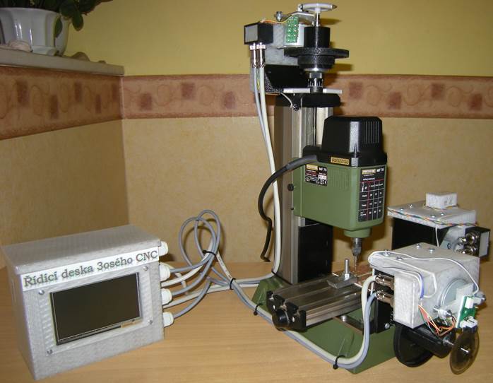
Description
Proxxon
MF70 micro miller can be easily converted to
a small, but precise 3-axial CNC machine using stepper motors and gears from three
old printers HP LaserJet 1018 or 1020 (probably also 1010, 1012, 1015 and 1022,
but not confirmed), three stepper motor driver boards X-NUCLEO-IHM03A1 (3 ea)
with powerSTEP01 drivers of STMicroelectronics and one
development board with LCD touch panel DISCO-F746NG with ARM Cortex M7 microcontroller
STM32F746NG of STMicroelectronics.
This set of four development
boards together with a new electronic shield containing a few cheap electronic
modules (RTCC, Wifi, Bluetooth, DC/DC step-down converter) will provide the following
control functions:
• Manual
control of CNC axes using LCD touch panel of DISCO-F746NG
• Automatic
execution of g-code from an integrated SD card of DISCO-F746NG
• Loading
g-code to the SD card remotely via USB, Ethernet, Wi-Fi or Bluetooth from
computers or mobile devices (mobile phones, tablets).
• Connecting
external sensors: end-stops on all axes, digital thermometers on all motors,
thermo-camera MLX-90621 and a camera STM32F4DIS-CAM for visual control of
machined parts.
• Data
and video transfer from the CNC back to a computer or a mobile device for
on-line diagnostics.
This simple and cheap CNC can be used for
making printed circuit boards (PCB), engraving and
milling wood, plastics or soft metals, especially in
school labs and hobby clubs. The effective working area of the final CNC is
approx. 130/43/74 mm X/Y/Z, micro-step resolution is 82 nanometers in all axes.
The developed electronic hardware and software is not limited to Proxxon MF70
only, but it can also be used for much more powerful types of 3-axial CNC
machines, with stepper motors up to 50 V / 10 A power limit each.
A short video of the first prototype of
the CNC with an example of a simple PCB milling and drilling can be seen here
for illustration:
Video
The following manual describes an
improved version of the first prototype and contains:
1.
Procedure for dismantling old HP LaserJet
printers.
2. Documentation
of the electronic hardware, including Eagle CAD files and the bill of materials
for the electronic shield with power supply, end-stop connectors, real-time
clock and calendar module (RTCC), digital thermometers connectors, I2C output
for thermo-camera and UART output for Wi-Fi and Bluetooth modules.
3. Documentation
of the mechanical hardware, including FreeCAD, STEP and STL files for their 3D
printing.
4. Procedure
for the assembly of the electrical and mechanical parts to the CNC setup (work
in progress).
5. Program
for DISCO-F746NG for manual control and for automatic g-code loading from a SD
card (work in progress).
6. Video
signal acquisition from a camera and a thermos-camera (work in progress).
7. Programs
for a PC and mobile devices for CNC remote control via USB, Ethernet, Wifi
and/or Bluetooth (work in progress).
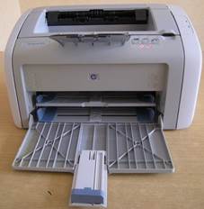
Dismantling HP LaserJet printers
The
described conversion of the Proxxon MF70 miller to a CNC machine requires
stepper motors Mitsumi
M49SP-2K and specific gears
from three HP LaserJet printers. These motors and gears are for sure used in HP
LaserJet 1018 and 1020 series, probably (but not confirmed) also in 1010, 1012,
1015 and 1022 series. You will need to get three pieces of these old printers,
the best for free from the electronic waste scrap yards, or eventually from
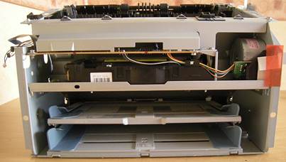
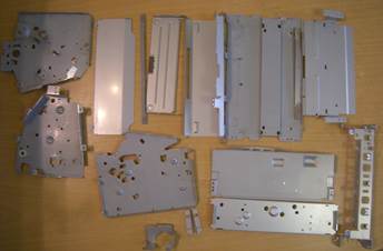
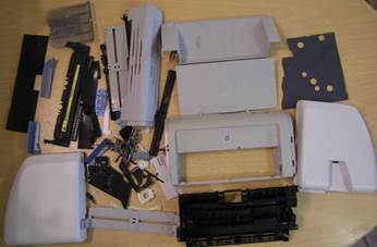
eBay. The photos below show disassembly of HP LaserJet 1020:
1.
Unscrew all screws and remove all plastic
parts from the printer. Pass the toner cartridge to the toner recycling
facility.
 c
c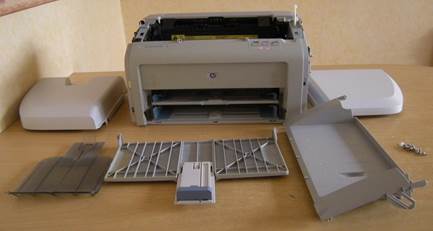
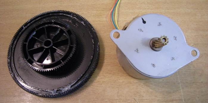
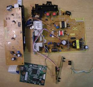
2. There
is a set of gears under a steel plate with a green electronic board on the
right side of the printer. You will need just the largest gear pointed to by
the red arrow bellow:
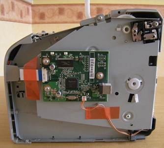
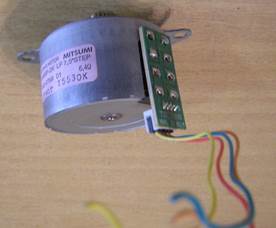
3. The
stepper motor is screwed to the other side of the metal plate. Unscrew it and
cut its leading wires at the powering board leaving as long wires as possible
with the connector at the motor.
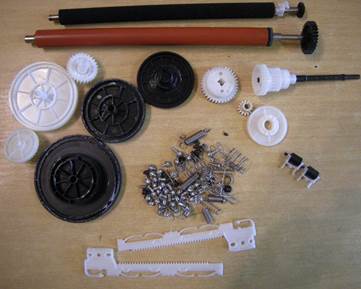
4. The
largest gear and the motor is all you will need from the printers for the CNC
machine.
5. You
will however get much more materials from the printers, which you can use in
other electronic or robotic projects. For example: lots of sheet metal, plastic
plates, linear and rotary gears, steel rollers, screws and springs, four
optical gates (switches/interrupters), electromagnet, and the best of all – the
laser unit for which use you can find recipes elsewhere (but work with care!)
Documentation
of the electronic hardware
You will need these parts for electronic
hardware of the CNC machine:
-
DISCO-F746NG - a development board
with STM32F746NG - ARM Cortex M7 series microcontroller, 4,3´´ LCD touch panel,
ethernet and USB connectors, camera connector, SD card slot, external SDRAM and
Flash memory chips, audio inputs and outputs, as the main control board and
user interface.
-
3 ea X-NUCLEO-IHM03A1 – development
boards with powerSTEP01 stepper motor driver, probably the most modern and
powerful stepper motor driver available (50VDC/10A), with SPI communication for
commands and diagnostics, up to 128 microsteps, 22-bit internal microstep
counter, voltage or current regulation, running with user-defined speed
profiles to selected positions etc.
-
Real-time
clock and calendar module (RTCC) ZS-042 with
DS3231 chip and AT24C32 EEPROM, communicating with the microcontroller of the
main control board via I2C and keeping the real time and date for the control
software (optional).
-
Wifi
module ESP8266 for wireless communication with the
CNC (optional).
-
Bluetooth
module HC-05 for an alternative wireless
communication with the CNC (optional). Please note that you can use either Wifi
or Bluetooth for wireless communication, not both of them simultaneously.
-
DC/DC
step-down module with LM2596 for effective 3V3
powering of the power-hungry WiFi module (avoiding overloading LDO of the main
control board).
-
3
ea DS18B20 digital thermometers for control of
the motor overheating.
-
MLX90621
thermocamera sensor for detection of the
tool overheating (optional).
-
STM32F4DIS-CAM
camera board for remote visual control of the
CNC operation (optional).
-
Stabilized power supply 12 VDC, at least
4 A output (e.g. ATX old casdesktop computer power supplies or LED strips power
supplies).
-
PCB board, single layer, approx. 100 x 85
mm.
-
15 ea 2-pin terminal connectors, pitch 5
mm (e.g. TB-5.0-P-2P)
-
SMD 0805 resistors 3k9 (1 ea) and 10k (4
ea)
-
Microswitches of any suitable and
miniature types as end stops (6 ea)
-
4-pin
microphone connectors for connecting motors
and thermocamera (4 ea)
-
5-pin
microphone connectors for connecting end
stops and digital thermometers (4 ea)
-
4-core shielded cable 4x0.25 mm2
for connecting motors and thermocamera (at least 5 meters)
-
5-core shielded cable 5x0.25 mm2
for end stops and digital thermometers (at least 5 meters)
-
PG9
plastic bushings for fixing cables entering control panel case (7 ea).
-
Auxiliary connectors: jumper (1 ea),
18-mm-long pins (32 ea), pin connectors with 2.54-mm-pitch (1 ea angled, 1 ea
straight), 4x2 connector with 2.54-mm-pitch (1 ea), power connector 2.5/5.5 mm
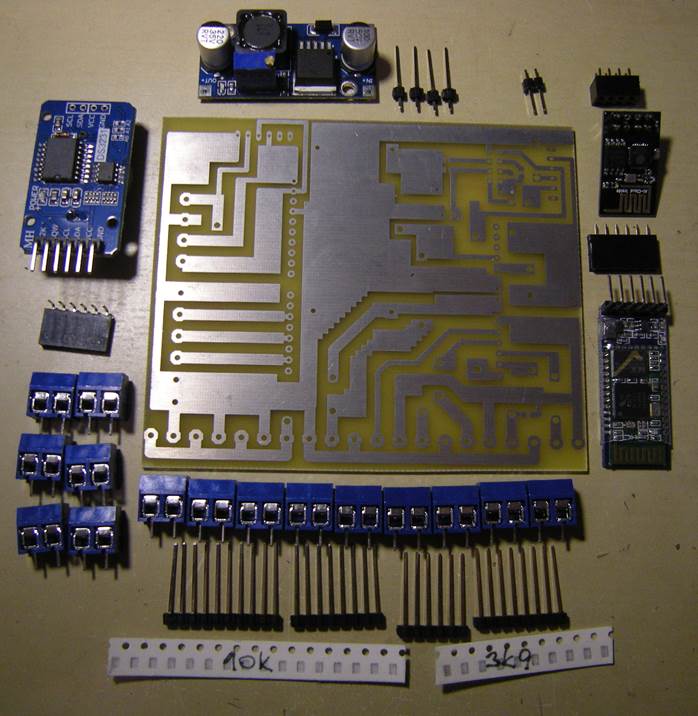
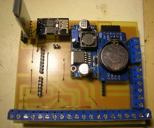
– see the photo with parts below.
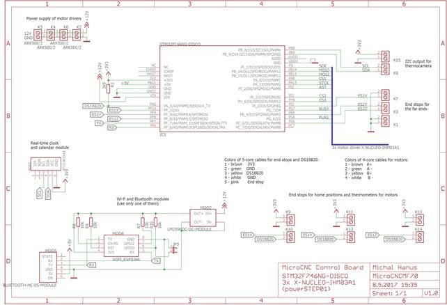
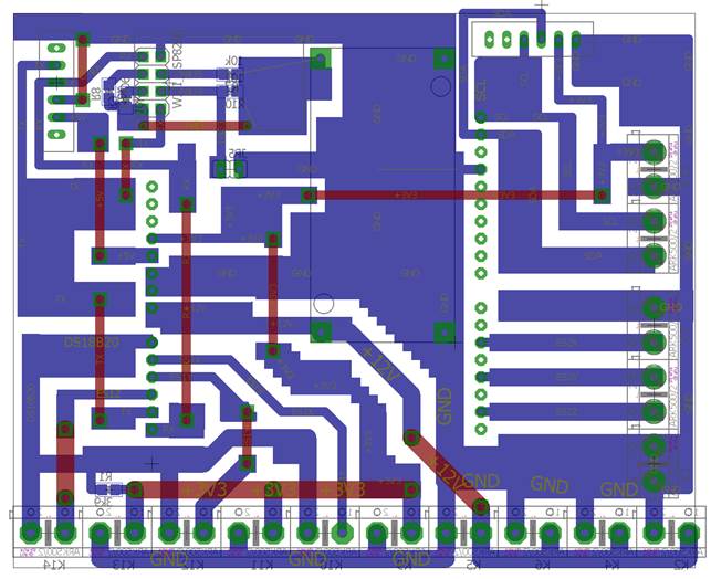
Make printed circuit board of the
electronic shield according to the following schemes (the Eagle CAD files are
attached below):
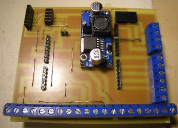
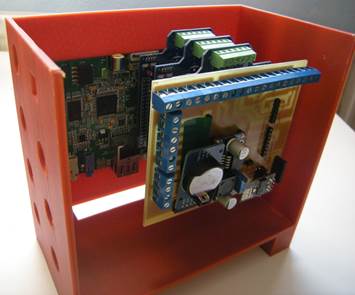
Assemble the PCBs with components as
shown in the schemes and the photos below.
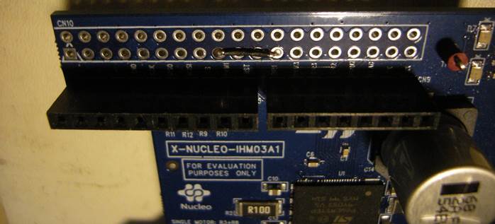
Take the three X-NUCLEO-IHM03A1 motor
driver boards and solder wires for chip select pins (CS) between these ports on
the board as follows:
Driver board No. 1: no connection (CS1
pin stays as ported on the original board)
Driver board No. 2: connect 9th
port of CN10 inner column with the 12th port at the same column and
bend the 8th pin (CS1) below the board to the right angle, making
CS2 pin connection.
Driver board No. 3: connect 9th
port of CN10 inner column with the 13th port at the same column and
bend the 8th pin (CS1) below the board to the right angle, making
CS3 pin connection.
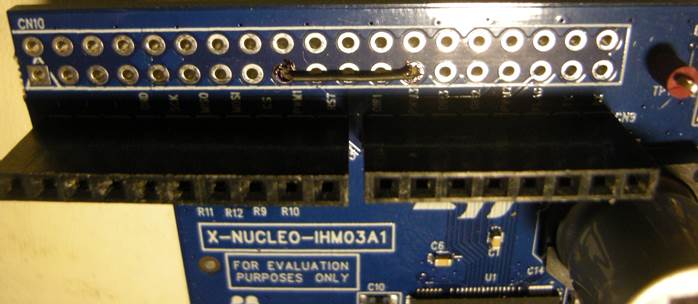
The electronic hardware is now ready for the
final assembly.
Documentation
of the mechanical hardware
This CNC conversion kit requires to
3D-print a few pieces of mechanical adapters for the Proxxon MF70 miller and a
case for the Control Panel. All these mechanical parts are designed in FreeCAD
- an open-source parametric modeler and are exported to STEP format for
compatibility with other CAD software, as well as to STL format for 3D
printing. All the design files are attached below.
As for 3D printing, the Control Panel
case can be printed from normal PLA with a low infill (20 %), but the parts to
be mounted on the CNC machine are recommended to be printed from PETG with a
high infill (50 %) to assure both good flexibility of PETG compensating for
irregularities of fixtures, and high mechanical strength of these fixtures.
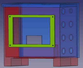
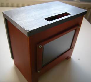
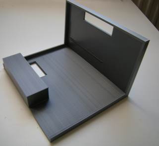
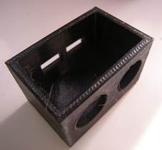
1. Control
Panel case consists of 3 parts - front panel, protection frame around the LCD
and the back panel.
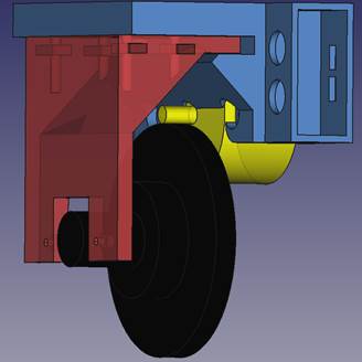
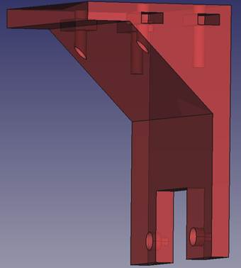
2. Fixtures
on the CNC axes consist of the following parts:
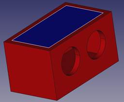
-
Axis holder (red)
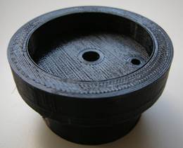
-
Axis handle (black) holding the gear.
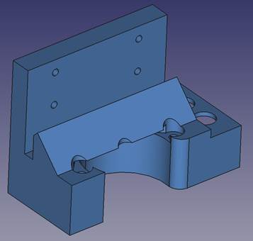
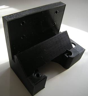
-
Motor holder (blue) for the stepper motor
(yellow)
-
Connector lid
Axis holder is screwed to the Proxxon
MF70 axes and holds the motor holder – it is designed specifically for the
respective axis.
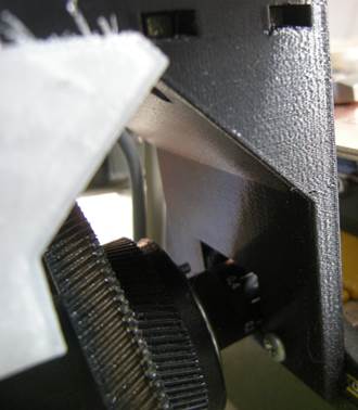
Axis handle
adapter (to be fixed to the manual handles of the Proxxon MF70 axes and holds
the gear) should be printed in 3 pieces to cover all the axes.
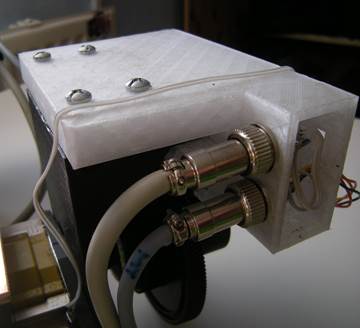
Motor holders are designed specifically
for each of the three axes and differ in size and position of the connector
boxes.
One more
connector box with a lid shall be printed separately to connect the far-end
stops and thermo-camera cables. Three more separate lids for the connector
boxes at the motor holders shall be printed as well.
The other chapters on final assembly and
software are still in progress, so if interested in this project, please come
back soon for more details or contact me at mikehanus@protonmail.com.
Files