Description
Old HP DeskJet PhotoSmart 1215 printer converted
to a can mixer or a wrist watch winder with a control unit based on PIC18F26K22
with alphanumeric LCD display, L293E bidirectional motor driver, rotation
counter, current measurement.
A few months ago, I made a simple watch-winder
for automatic wrist watches of my neighbor’s collection. The automatic wrist
watches don’t need a battery as they are being wound up mechanically by hand
movement on everyday normal use. Because my neighbor doesn’t have enough hands
to wear all his collection at once, he needed a machine to wind them up from
time to time. I was afraid that the first simple model of the watch winder would
not survive long and so I started to work on a new improved version, which
could wind up several wrist watches with a selection of rotation speed,
direction and time using a control unit with LCD and buttons.
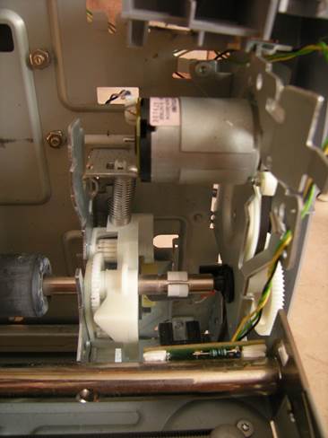
For mechanical parts I used an old
salvaged printer HP DeskJet PhotoSmart 1215 taking its steel
frame and geared DC motor with rollers for paper feed. Its printing head was
used as a restainer. Originally I wanted to use its integrated encoder with
1800 tics per rotation but it showed up that the maximum speed its original
encoder circuit can handle is about 2 rps only. So
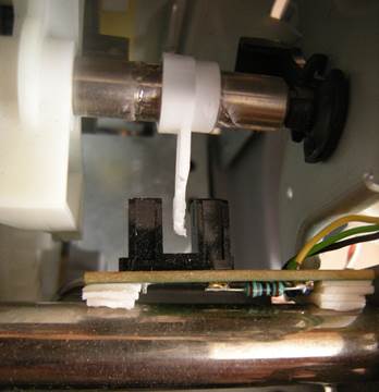
I had to make a new rotation counter from a photointerrupter used somewhere
else in this printer and to glue a piece of plastic to a shaft of the roller.
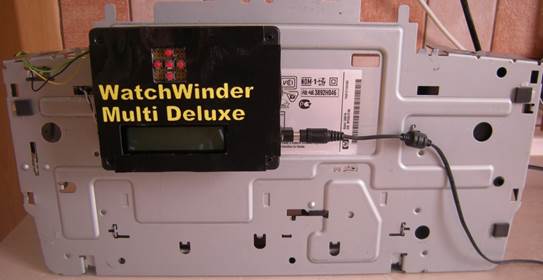
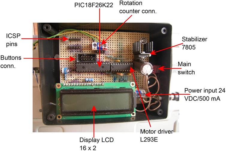
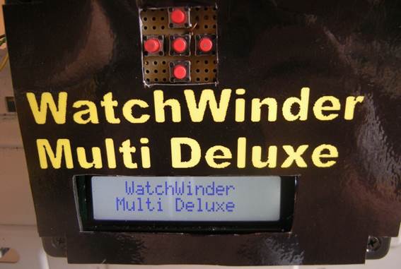
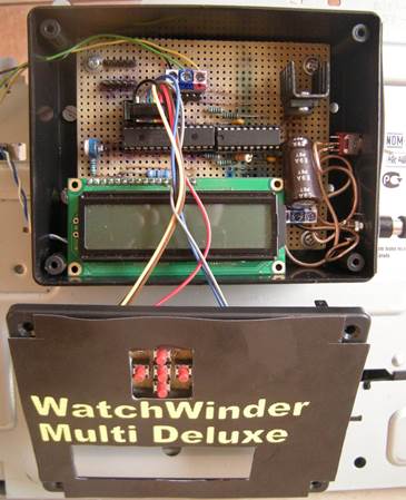
The control unit is positioned at the back
side of the printer frame and it is powered by a 24 VDC/500 mA printer adapter.
The user interface is formed by an alphanumeric LCD display
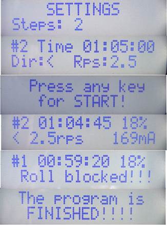
and five direction buttons. In the first step, the user enters the number of
rotation steps. Then the user sets rotation time, direction and speed in each
step. After confirming the start, the program measures the time of each
rotation and regulates its PWM output to the motor to keep the rotations at the
required value. The program also measures motor current and turns off the
output when a value over 500 mA is detected. The motor is also stopped if the
rotation drops below 0.5 rps. The effective rotation range is 1.0 – 10.0 rps.
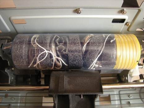
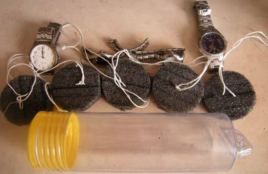
The wrist watches are inserted into a plastic tube
from a small hobby drill and separated by foam spacers. The mixer can have
other uses as well, for example mixing of paint spray cans, food cans or even
drinks J.
Images
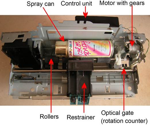
Front view:
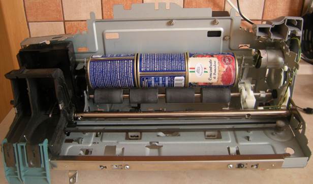
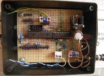
Back view:
Motor with gears:
Plastic tube with wrist watches and
foam spacers:
Parts
The control unit parts
-
MCU: PIC18F26K22
-
Inputs:
o 5
buttons for LCD control
o Photointerrupter
for rotation counting
o Motor
current measurement
via L293E
-
Outputs:
o Bidirectional
motor driver L293E for a printer roller motor
o LCD
alphanumeric
display 16x2
-
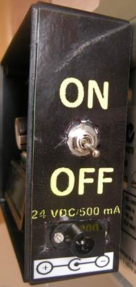
Power: 24 VDC/500 mA printer adapter, 5 VDC
via 7805 linear stabilizer for MCU and the rest.
-
PCB: universal line PCB (e=0.1´´)
Display
Program windows:
Table
of components:
|
Code
|
Type
|
Parameters
|
Function
|
|
C1
|
capacitor
|
ceramic 100 nF
|
driver power filter
|
|
C2
|
capacitor
|
ceramic 100 nF
|
driver power filter
|
|
C3
|
capacitor
|
electrolytic 630 µF
|
power filter and buffer
|
|
C4
|
capacitor
|
SMD 0805 ceramic 10 µF
|
7805 output capacitor
|
|
C5
|
capacitor
|
SMD 0805 ceramic 100 nF
|
7805 input capacitor
|
|
C6
|
capacitor
|
SMD 0805 ceramic 100 nF
|
7805 output capacitor
|
|
C7
|
capacitor
|
ceramic 100 nF
|
MCU power filter
|
|
D1
|
diode
|
UF4007
|
power polarity protection
|
|
D2-D5
|
diode
|
UF4007
|
driver output protection
|
|
DS1
|
LCD display 16x2
|
RC1602B2-GHW-CSX
|
setting and displaying program parameters
|
|
FU1
|
polymer fuse
|
500 mA
|
overcurrent and polarity protection
|
|
IC1
|
stabilizer
|
7805
|
5V power source
|
|
IC2
|
MCU
|
PIC18F26K22
|
main microcontroller
|
|
IC3
|
motor driver
|
L293E
|
bidirectional motor driver
|
|
JP1
|
pin header
|
|
ISCP programming
|
|
JP2
|
pin header
|
|
UART communication (not used)
|
|
K1
|
terminal
|
ARK500/3
|
main power connector
|
|
K2
|
terminal
|
ARK500/2
|
motor connector
|
|
K3
|
terminal
|
ARK500/3
|
rotation counter connector
|
|
K4
|
terminal
|
IDC10
|
connector to the setting buttons
|
|
M1
|
motor
|
HP DJ PhotoSmart 1215 paper feed motor with gears
|
main motor
|
|
PI1
|
photointerrupter
|
from a HP printer
|
rotation counter
|
|
R1
|
resistor
|
2.2 Ω
|
current shunt resistor
|
|
R2
|
resistor
|
180 Ω
|
photointerrupter
input resistor
|
|
R3
|
resistor
|
1 kΩ
|
motor driver input protection
|
|
R4
|
resistor
|
1 kΩ
|
motor driver input protection
|
|
R5
|
resistor
|
1 kΩ
|
motor driver input protection
|
|
R6
|
trimmer
|
5 kΩ
|
LCD display contrast setting
|
|
R7
|
resistor
|
1 kΩ
|
LCD display contrast setting
|
|
R8
|
resistor
|
68 Ω
|
LCD display background light
|
|
R9
|
resistor
|
1 kΩ
|
MCU analog input protection
|
|
R10
|
resistor
|
2.2 kΩ
|
photointerrupter
output resistor
|
|
S1
|
switch
|
toggle switch
|
main power switch
|
Schemes
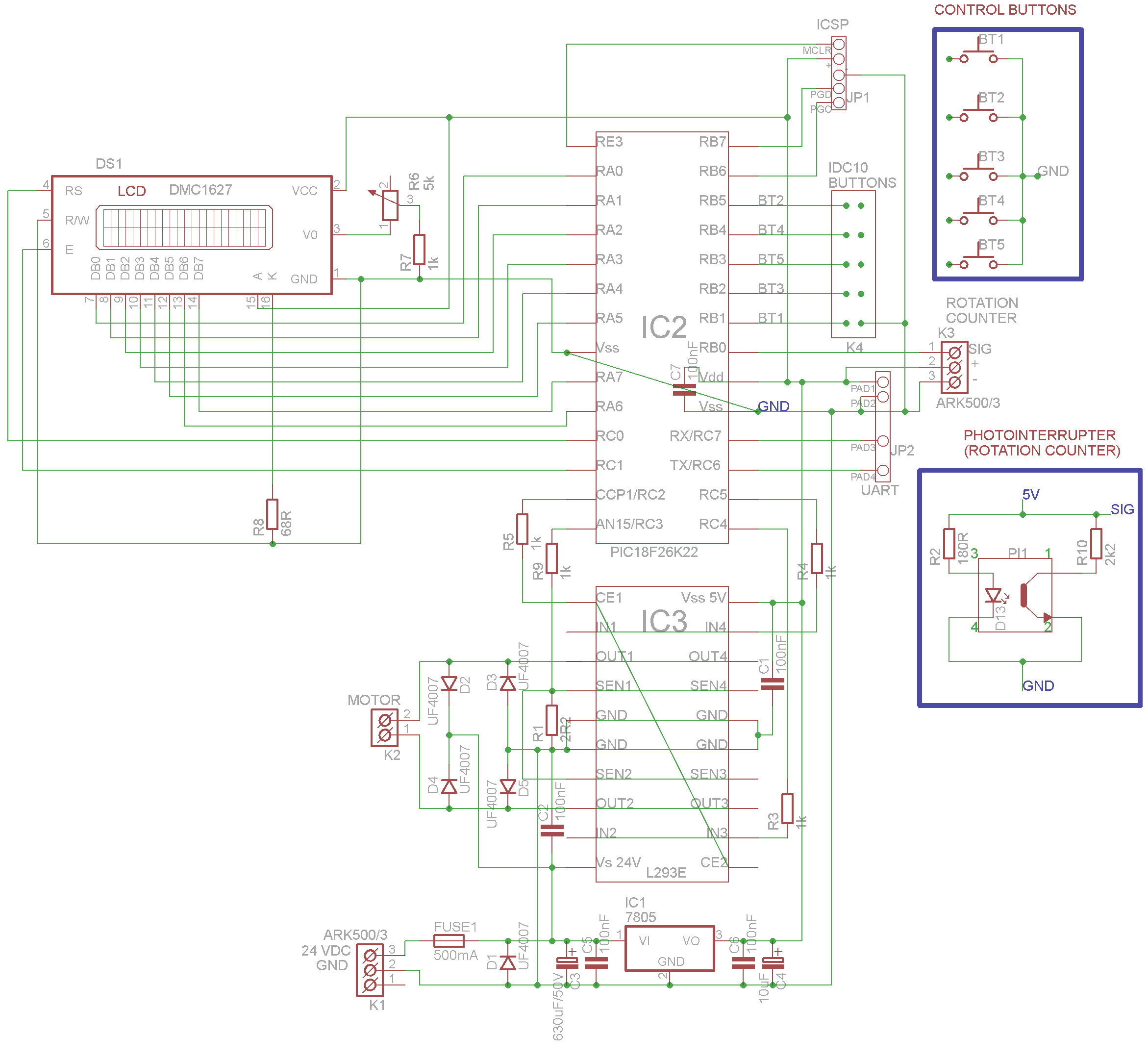
Functional scheme:
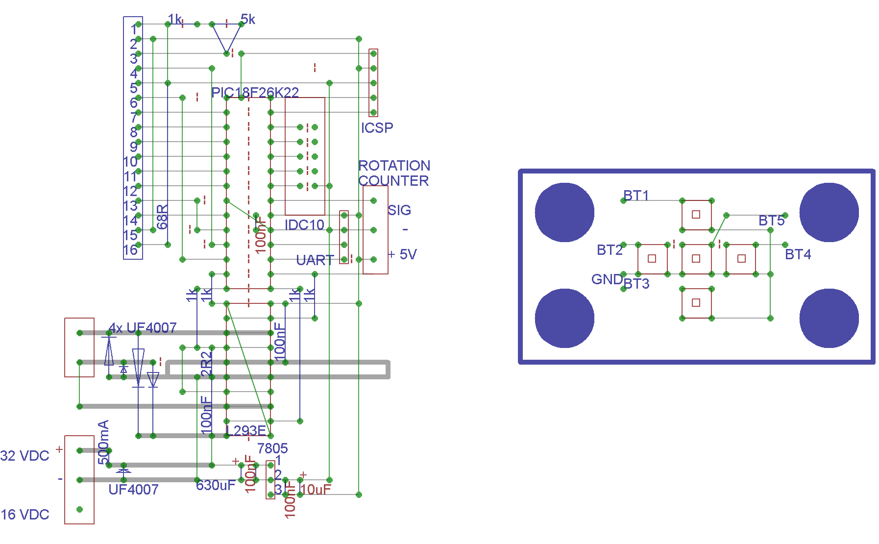
Soldering scheme
(universal line PCB; e=0.1´´):
Control unit
Control unit interior:
PCB connections:
Control unit right side:
Rotation counter with
photointerrupter: