Description
Non-MCU walking robot hacked from Tin
Can Robot toy, avoiding obstacles using homemade IR range sensors.
This is my very first robot, which I made
when I was nine. For my birthday I got a simple walking robot Tin
Can Robot, which just moved forward and I wanted to
hack it so that it could move both directions, change its speed and avoid
obstacles. The hack is based on design ideas of my dad and brother, I just did
PCB drawing, assembly, soldering and overall setup.
Function
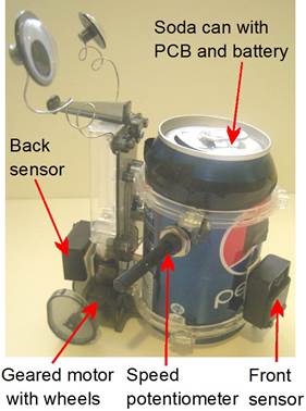
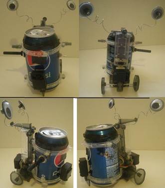
The robot is driven by a single geared DC
motor and holds a 12-oz soda can. Due to the egg-shaped wheels, its movement
resembles a drunken sailor. Its original one AA battery was replaced by a
battery-pack of four AA batteries, partially depleted from other toys, to get 4.5
– 5.5 V input voltage. The battery-pack was inserted inside the cut soda can with
a PCB. The PCB (universal, line, e=0.1´´) contains a bidirectional motor driver
L293D, three 555 ICs for adjusting the sensors and motor speed control and
74HC74 flip-flop IC for motor direction changes.
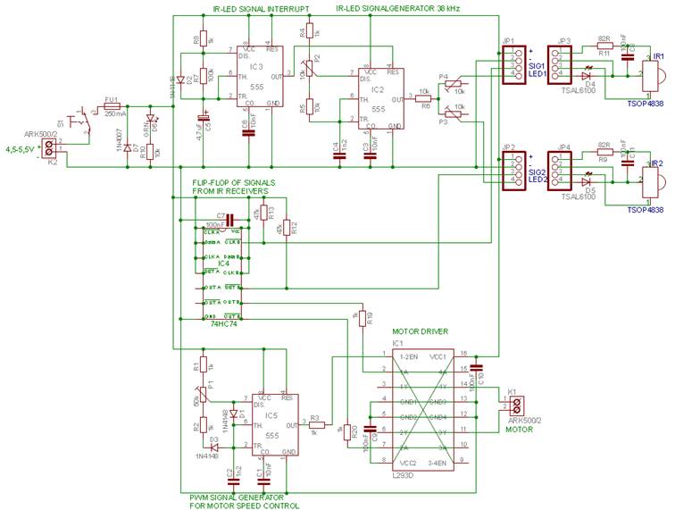
Motor speed is controlled by 50k potentiometer
(P1) at 555 (IC5) input circuit. IC5 sends PWM signal to a bidirectional motor
driver L293D, which changes direction of the motor based on a signal from a
flip-flop 74HC74 (IC4). The flip-flop changes its output (10 or 01) when it
gets a signal from one of IR sensors TSOP4838 positioned on a front side and a
back side of the robot in separate boxes. The sensors are modulated for 38 kHz
IR signal, which is emitted by IR LEDs placed next to the sensors. The 38 kHz
IR signal is generated by another 555 (IC2) using a 10k potentiometer (P2) for
precise frequency adjustment. A current in each LED can be set by 10k
potentiometers (P3, P4), what defines the range for the obstacle detection (2 -
20 cm). Because TSOP4838 IR sensors can be overloaded by a long 38 kHz signal,
the signal generator (IC2) must be interrupted by another 555 (IC3).
The robot walks forward until it
approaches the nearest object, the front IR sensor gets a reflection of the IR
LED beam, the flip-flop IC changes the direction of the motor driver and the
robot walks back until back sensor gets the reflection and then the cycle
repeats.
Table of components
|
Code
|
Type
|
Parameters
|
Function
|
|
C1
|
capacitor
|
ceramic 10 nF
|
555 stabilization
|
|
C2
|
capacitor
|
ceramic 1n2
|
setting 555 timing parameters
|
|
C3
|
capacitor
|
ceramic 100 nF
|
555 stabilization
|
|
C4
|
capacitor
|
ceramic 1n2
|
setting 555 timing parameters
|
|
C5
|
capacitor
|
electrolytic 4.7uF
|
setting 555 timing parameters
|
|
C6
|
capacitor
|
ceramic 100 nF
|
555 stabilization
|
|
C7
|
capacitor
|
ceramic 100 nF
|
74HC74 power filter
|
|
C8
|
capacitor
|
ceramic 100 nF
|
RC filter for IR sensor
|
|
C9
|
capacitor
|
ceramic 100 nF
|
L293D power filter
|
|
C10
|
capacitor
|
ceramic 100 nF
|
L293D power filter
|
|
C11
|
capacitor
|
ceramic 100 nF
|
RC filter for IR sensor
|
|
D1
|
diode
|
1N4148
|
setting 555 timing parameters
|
|
D2
|
diode
|
1N4148
|
setting 555 timing parameters
|
|
D3
|
diode
|
1N4148
|
setting 555 timing parameters
|
|
D4
|
diode
|
TSAL6100
|
IR LED front
|
|
D5
|
diode
|
TSAL6100
|
IR LED back
|
|
D6
|
LED
|
green 5 mm
|
power indication
|
|
D7
|
diode
|
1N4007
|
polarity protection
|
|
FU1
|
polymer fuse
|
250 mA
|
overcurrent protection
|
|
IC1
|
motor driver
|
L293D
|
bidirectional motor driver
|
|
IC2
|
integrated circuit
|
555
|
IR LED signal generator 38 kHz
|
|
IC3
|
integrated circuit
|
555
|
IR LED signal interrupt generator
|
|
IC4
|
flip-flop
|
74HC74
|
Flip – flop of signals from IR receivers
|
|
IC5
|
integrated circuit
|
555
|
PWM signal generator for motor speed control
|
|
IR1
|
IR receiver
|
TSOP4838
|
detection of reflected IR LED signal
|
|
IR2
|
IR receiver
|
TSOP4838
|
detection of reflected IR LED signal
|
|
JP1
|
header
|
|
front sensor connection headers
|
|
JP2
|
header
|
|
back sensor connection headers
|
|
JP3
|
header
|
|
front sensor connection headers
|
|
JP4
|
header
|
|
back sensor connection headers
|
|
K1
|
terminal
|
ARK500/2
|
motor terminals
|
|
K2
|
terminal
|
ARK500/2
|
power terminals
|
|
M1
|
motor
|
|
|
|
P1
|
potentiometer
|
50 kΩ
|
motor speed adjustment
|
|
P2
|
trimmer
|
10 kΩ
|
adjusting 38kHz signal
|
|
P3
|
trimmer
|
10 kΩ
|
adjusting IR LED current
|
|
P4
|
trimmer
|
10 kΩ
|
adjusting IR LED current
|
|
R1
|
resistor
|
1 kΩ
|
setting 555 timing parameters
|
|
R2
|
resistor
|
1 kΩ
|
setting 555 timing parameters
|
|
R3
|
resistor
|
1 kΩ
|
motor driver input protection
|
|
R4
|
resistor
|
1 kΩ
|
setting 555 timing parameters
|
|
R5
|
resistor
|
10 kΩ
|
setting 555 timing parameters
|
|
R6
|
resistor
|
10 kΩ
|
IR LED current limiting
|
|
R7
|
resistor
|
100 kΩ
|
setting 555 timing parameters
|
|
R8
|
resistor
|
1 kΩ
|
setting 555 timing parameters
|
|
R9
|
resistor
|
82 Ω
|
RC filter for IR sensor
|
|
R10
|
resistor
|
10k Ω
|
LED current limiting
|
|
R11
|
resistor
|
82 R
|
RC filter for IR sensor
|
|
R12
|
resistor
|
47 kΩ
|
pull – up for a signal to74HC74
|
|
R13
|
resistor
|
47 kΩ
|
pull – up for a signal to74HC74
|
|
R19
|
resistor
|
1 kΩ
|
motor driver input protection
|
|
R20
|
resistor
|
1 kΩ
|
motor driver input protection
|
|
S1
|
switch
|
toggle switch
|
power switch
|
Functional scheme
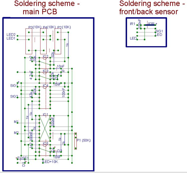
Soldering scheme
Soldering scheme
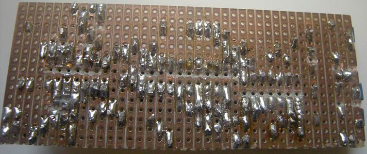
(universal line PCB; e=0.1´´):
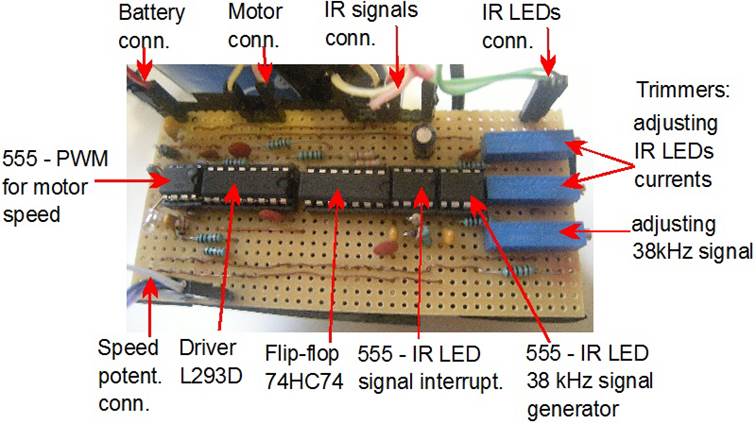
PCB photos
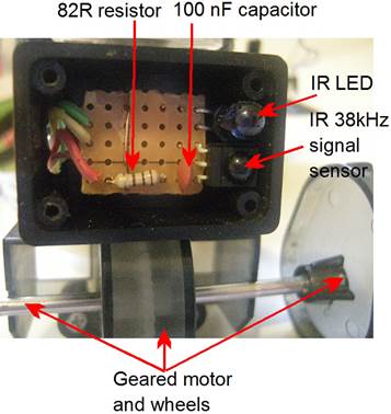
Back sensor photo
Owerall views
From
today’s perspective, when I already know how to program MCUs, the electronics
of this robot seems to be quite complicated compared to what it actually does
but it was fun and I liked to solder large PCBs J.
Files&Codes