Description
A doorbell for unwanted guests (aka Useless
Machine) with PIC12F1840, a mechanical finger moved by a geared DC motor, a
L293D driver, a limit switch and a speaker.
Main parts
-
MCU: PIC12F1840
-
Inputs:
o Activating
switch: a wall-type rocker
o Limit
switch: a lever-type salvaged from a printer
-
Outputs:
o Bidirectional
motor driver: L293D
o Geared
DC motor salvaged from a scanner
o 0.5W
speaker switched by PWM via IRLB8743 N-MOSFET
o Blue
LED
-
Power: 9 VDC (6x AA battery) for a motor
and speaker, 5 VDC via MCP1702 linear stabilizer for MCU and the rest.
-
PCB: universal line PCB (e=0.1´´)
Table of components
|
Code
|
Type
|
Parameters
|
Function
|
|
C1
|
capacitor
|
electrolytic 470 µF / 50 V
|
power buffer
|
|
C2
|
capacitor
|
ceramic 100 nF
|
power filter
|
|
C3
|
capacitor
|
ceramic 1 µF
|
MCP1702 stabilization
|
|
C4
|
capacitor
|
ceramic 1 µF
|
MCP1702 stabilization
|
|
C5
|
capacitor
|
ceramic 100 nF
|
driver filter
|
|
C6
|
capacitor
|
ceramic 100 nF
|
driver filter
|
|
C7
|
capacitor
|
ceramic 100 nF
|
MCU filter
|
|
C8
|
capacitor
|
ceramic 220 nF
|
sound RC filter
|
|
D1
|
diode
|
1N4007
|
polarity protection
|
|
D2
|
LED
|
blue
|
indication of motor movement
|
|
FU1
|
polymer fuse
|
500 mA
|
overcurrent and polarity protection
|
|
IC1
|
MCU
|
PIC12F1840
|
microcontroller
|
|
IC2
|
stabilizer
|
MCP1702-5000, 5 V, 250 mA
|
5 V power supply
|
|
IC3
|
driver
|
L293D
|
bidirectional motor driver 1.2 A
|
|
JP1-JP2
|
jumpers
|
|
MCU isolation at programming
|
|
Q1
|
transistor
|
IRLB8743, N-MOSFET, 30 V / 150 A, RDS 3.2
mΩ
|
switching of speaker for sound generation
|
|
R1
|
resistor
|
1 kΩ
|
sound RC filter
|
|
R2
|
resistor
|
47 Ω
|
speaker current limitation
|
|
R3
|
resistor
|
1 kΩ
|
driver input protection
|
|
R4
|
resistor
|
10 kΩ
|
LED current limitation
|
|
R5
|
resistor
|
1 kΩ
|
driver input protection
|
|
R6
|
resistor
|
1 kΩ
|
driver input protection
|
|
SP1
|
speaker
|
8 Ω/0.5 W
|
barks J
|
|
SW1
|
limit switch
|
from a printer
|
stops finger movement
|
|
SW2
|
activating switch
|
wall switch
|
starts finger movement
|
|
SW3
|
switch
|
toggle switch
|
main power switch
|
Function:
When an activating switch SW2 is pressed,
LED lights on, the speaker barks and the motor starts moving the mechanical finger
to turn off the switch again. Then the finger moves back until it hits a limit
switch SW1 that stops its movement or the activating switch SW2 is pressed
again.
Functional scheme
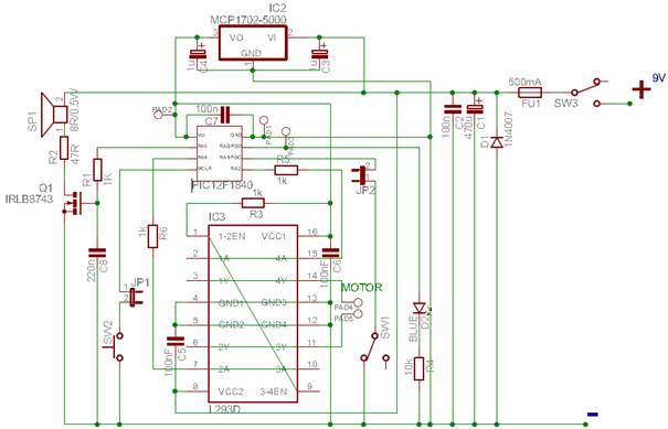
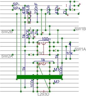
Soldering scheme
Soldering scheme
(universal line PCB; e=0.1´´):
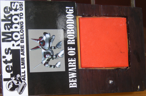
Photos:
Top of the box:
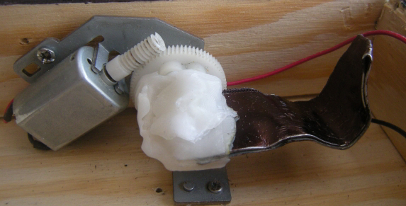
Motor with a mechanical finger
(held by polymorth):
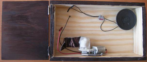
Empty box with a motor and a speaker:
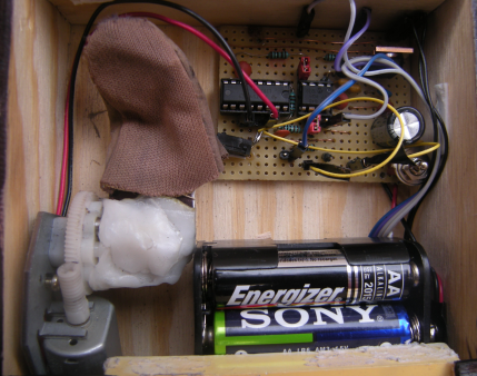
Box inside:
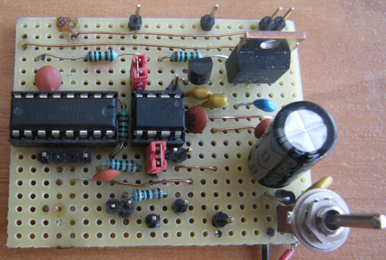
PCB top:
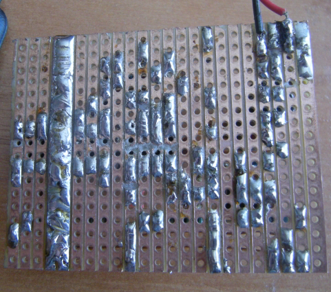
PCB bottom:
Files&Codes